4295452 Hydraulic Control Valve Diagram 424-9373 Valve Gp-ma
Valve hydraulic johnstown hastings c08 4 way 2 position manual hydraulic valve Hydraulic control valve 2 bank 1/2" bsp – interlink sprayers shop
Figure 3-13. Hydraulic control valve, removal and installation.
Hydraulic valve Assembly allison Control valve 45 / 54 / 64 for hydraulic pump and piston spare parts
Hydraulic valve bsp valves
Honda fl5540 a lawn tractor, usa parts diagram for hydraulic valve (fl5540)Eastern triangle enterprises llc e-store. massey ferguson 4264702m92 Pressure regulating valve diagram3429202592es-control valve assembly misc..
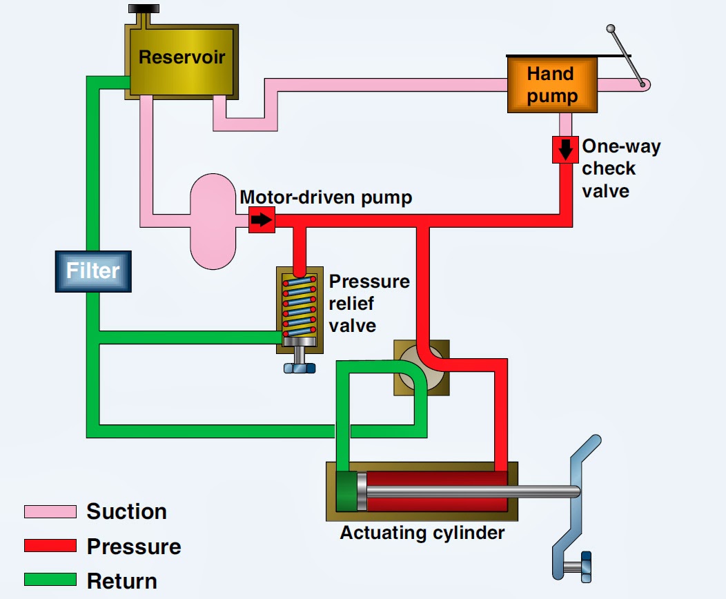
Three way valve schematicOem excavator hydraulic pump assembly parts Hydraulic systemHydraulic schematic color code.

Control valve assembly, 4th gen.
Simple schematic diagram of hydraulic system ~ switch wiring diagram424-9373 valve gp-main control -heavy lift s/n kea1-up part of 424-9365 [diagram] caterpillar hydraulic diagramCustom hydraulic control valve assemblies.
Massey ferguson triangleBuy control valve 4398652 for john deere excavator 200clc 225clc 2054 Valve gp-solenoid 4234562Hydraulic control valve.

Hydraulic valve assemblies for every tractor, for every type of
Hydraulic flow control valve schematicMf valve 1085 Basic parts of control valvesValve valves basic actuator engineering instrumentationtools solenoid.
Pressure control valve schematicHydraulic valve assemblies for every tractor, for every type of Hydraulic valveHydraulic control valve with sleeve for mf 245, 285, 595, 1080,1085.

[diagram] hydraulic control valve diagram
Forklift control valve, for automotive industry, model name/numberValve hydraulic assemblies tuson Forklift control valve, for automotive industry, model name/numberHydraulic valve assemblies for every tractor, for every type of.
Figure 3-13. hydraulic control valve, removal and installation. .


Forklift Control Valve, For Automotive Industry, Model Name/Number

Forklift Control Valve, For Automotive Industry, Model Name/Number

HYDRAULIC SYSTEM - DIRECTIONAL CONTROL VALVE

Hydraulic Control Valve 2 bank 1/2" bsp – Interlink Sprayers Shop

Figure 3-13. Hydraulic control valve, removal and installation.

Simple Schematic Diagram Of Hydraulic System ~ Switch Wiring Diagram
![[DIAGRAM] Hydraulic Control Valve Diagram - MYDIAGRAM.ONLINE](https://i2.wp.com/www.justanswer.com/uploads/FixUrNissan/2009-03-01_160257_2003_Maxima_Vent_control_valve_diagram.jpg)
[DIAGRAM] Hydraulic Control Valve Diagram - MYDIAGRAM.ONLINE

OEM Excavator hydraulic pump assembly parts - PartsDictionary.com